The Time Meter module measures the samples and time (in milliseconds) between various events/values to enable measurement of the time an envelope takes (from 0V back to 0V), between two values to measure audio or low frequency oscillators, gate width or between two triggers.
The measurement has multiple modes which include measuring gates, two separate trigger inputs, zero-crossing (e.g the measure cycle-time on waves), envelope specific measurement (0V through to return to 0V) or a more flexible value-based setting with multiple modes.
Measuring gates, triggers, longer CV changes between different voltages and envelopes is accurate to the internal sample rate of Voltage Modular, while measuring waveform cycle time accurately (especially for audio waveforms) can be more challenging depending on the waveform being measured.
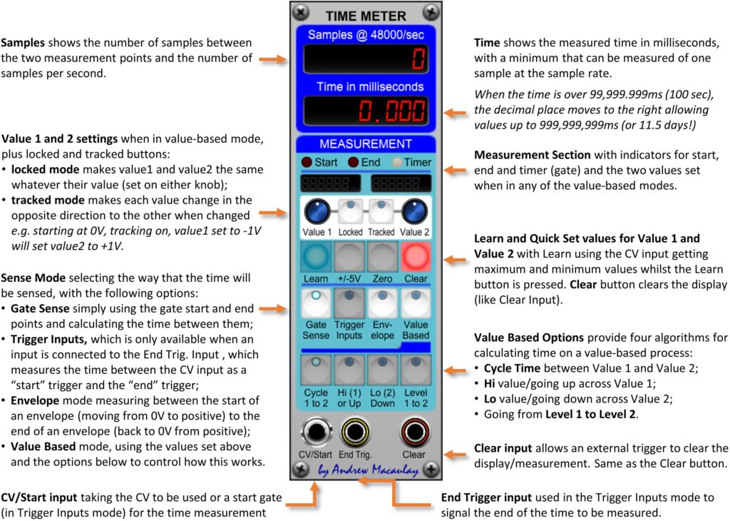
Note that each patch cable in a signal chain in Voltage Modular introduces a one sample delay of the signal. With the internal sample rate at 48000 samples/second, this delay is less than 0.021ms and should not be an issue in normal circumstances. However, this may become noticeable when measuring the time between triggers, etc. For example, if using the direct output of the I/O Panel Trigger on CV/Start and a trigger processed by one or more modules for the End Trig. where there will be two or more patch cables used, the sample count and time displayed can be one or more samples than expected. Modules such as the Trigger Delay cope with this behaviour by having a Trigger Out signal from the module which you can then measure against and you can also use the free Patch Bay module to add the necessary patch cables to give the sample-level accuracy.