There are a number of standard approaches used throughout Andrew Macaulay’s Modules. As many modules are deliberately stripped back, these might not be completely obvious to start with, but once you’ve understood the approach in one module, it will typically be consistent across modules. This section provides a breakdown of some of these common approaches, to help you as you start using the modules.
Clock In / Host Sync
In many of the time-based or beat-based modules, you will see reference to Host Sync and/or Clock In and a Speed/Divider knob. The approach here is simple but flexible:
- Host Sync is driven by the host or DAW speed as recognised within Voltage Modular. Effectively this bypasses the need to use the SYNC out on the main input/output panel and a Sync Divider. If nothing is connected, this defaults 120 bpm.
- Clock In allows the timing to be calculated from a gate or trigger input. This takes a couple of gates/triggers to start working (for obvious reasons) and can adjust as the clock is changed – although large changes to the clock may take a few beats to settle down again.
- Time/Speed/Divider Knob allows multiplication and division of the speed or time from these inputs – from 1/16 to x16. When used on beat-based modules, the speed increases clockwise, when on time-based modules, the length of time increases clockwise.
BPM CV Inputs and Outputs
CV signals for BPM are used on a number of modules, both as outputs and inputs. In all these cases, the mapping is 1 Volt = 100 bpm, with an expected range of 0V – 5V (>0bpm to 500bpm) although it does not limit it and only if over 1000bpm does it trap it. If at 0V or negative, it is ignored. This is often included as an option alongside Host and Clock In sync for beat-based modules.
Standardised BPM/Clock Sync User Interface
From Release 6, the user interface for BPM/Clock Sync inputs for most modules has been simplified with a single, multi-purpose jack input and a single button switch to change modes. Older preset will be migrated where possible (where it is clear what the intention was) but note that some older presets may have settings which can’t be migrated, and a legacy mode for the UI will be presented (see later).
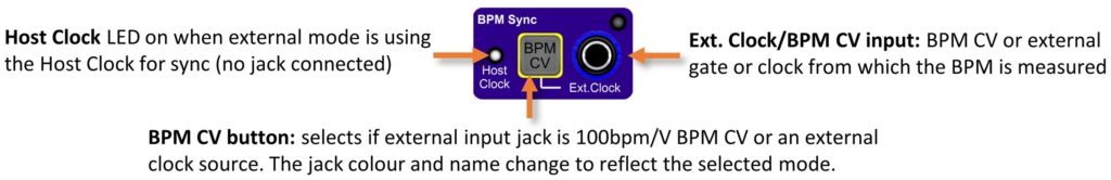
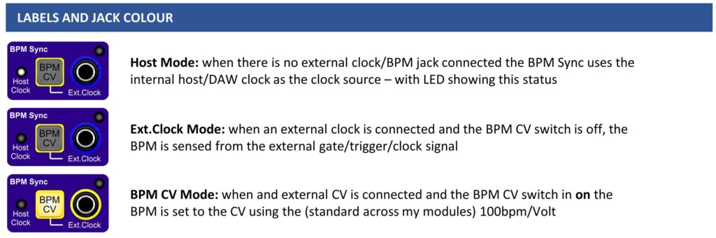
Depending on the state of the jack connection and the BPM CV button, the label for and colour of the jack socket change to make it clear which mode the BPM Sync input is currently in. The following images show the three states for the BPM/Clock Sync input jack.
Legacy Mode
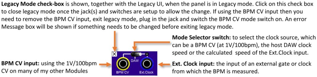
If a preset is opened that cannot be directly migrated to the new UI, e.g. with BPM CV jack connected or with an unusual combination of jacks connected and mode (e.g. Ext.Clock jack connected and mode set to DAW), the Legacy Mode UI will replace the standard UI:
Speed/Divider Knob LED
On many beat-based modules, there is an LED with the Speed/Divider knob which shows the speed of the internal gate after the speed/divider factor is applied. These will typically (and in time, consistently) flash Blue for the calculated beats and will go Red if a 0bpm signal is received.
Module Bypass Behaviour
Many of the modules support the Module Bypass functionality, where appropriate. Depending on the functionality of the module, the behaviour differs, but the general approach for Bypass mode is that:
- for audio paths (or audio capable paths), bypass mode passes through the audio input to the audio output;
- for CV processing, bypass mode passes the input CV to the output where this makes sense;
- for Envelopes this typically means passing the gate signal to the envelope output;
- for Gate/Trigger modules this typically means passing the input gate/trigger to the output; and
- for modules that simply generate signals and do not process signals, the outputs are often simple nulled.
Voltage Modular I/O Panel Inputs
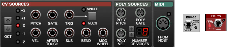
Many modules have relevant inputs that default (when no jack connected) to the DAW/external controller inputs provided from the I/O Panel (CV Sources, Poly Sources, MIDI). Typically, these inputs will be shown on the module with the input name in a rounded box and arrow to the jack which it is connected to and in some cases, additional switching to disable the internal connection is provided (see below for examples).
Module Customisation
There are a series of personalisation/customisation options available for modules across many of the modules:
1. Mid-Point for Log-Scale Time Controls
Modules which have time-based controls now have the ability to change the mid-point for the logarithmic behaviour of the knobs. This applies to e.g. Delay, Attack, Hold, Decay, Sustain and Release times on envelopes, Gate Times on the Gate Processor (Re-Gater) Module and the Delay and Fade times on the new CV Delay modules.
This setting is available through a “pop-up” configuration box and allows the mid-point to be set to 500ms, 750ms, 1000ms, 1250ms, 3000ms (what is effectively a “legacy” mode) as well as to a standard linear mode. The legacy mode is automatically set (on existing modules) when loading presets from previous versions so that their behaviour is as expected.
NOTE that the knobs store and act on (saving and loading) the value of the knob, not the position in any specific mode. As a result, when using the Remote Control module (or similar modules) that control the VALUE of any knob from a CV, it is often best to set the knob into the Linear mode so that the behaviour of the knob is consistent with the indicator on the Remote Control. Note that, unlike the Remote Control module, the PERFORM knobs control the POSITION of the knob, and so the resulting value will be affected by the setting of the mid-point value.
2. Minimum Gate/Envelope Times
Minimum Attack Time, Decay/Release Time and Gate Time switches are also available on many modules such as Envelopes, Gate processing modules, Ratcheting, etc. and allows the default behaviour of allowing the times to be 0ms (a simple trigger for gates) or a minimum of 2ms, even if the control plus a CV make it less. This ensures that the gate will fully open the envelope on Cherry Audio’s standard Envelope Module which has a 2ms minimum Attack time, and will remove the possible clicks from envelopes when used at 0ms.
Accessing the Settings
Where a setting is not directly available on the module, the settings will be available through a “pop-up” configuration box accessible by pressing the cogwheel  settings/config button to open the control. Full details of the settings and customisation options are available on the Customisation Options help page.
Global UI Customisation
There are a series of customisation options available for all modules related to the display of Release Notes and of the custom popup “tooltip” style help in some modules. These settings are accessible by right clicking on the logo ![]() . Full details of the options are available on the Customisation Options help page.
. Full details of the options are available on the Customisation Options help page.